Thinband Applications and Technical Data
Thinband Operating Factors

Use as low a watt density rating – as your application will permit. A close match of the heat supplied (to the actual requirements) will reduce temperature overshoot and cycling, and will increase the life of your band heater.
Calculate Safe Maximum Wattage for Your Heater…
Heated Area x Maximum Watt Density:
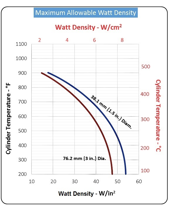
Determine the maximum watt density of your heater from graph on this page. (Note: The curves are based on narrow heaters mounted on a smooth, steel cylinder.)
Calculate the heated area of your barrel heater: Subtract the no-heat area from the total area in contact with the cylinder (3.14 x I.D. x width). Subtract the no-heat area at the terminals and any additional no-heat areas caused by holes, slots and over-sized gaps.
Apply the necessary correction factors:
• For heaters 57 mm (2.25 in.) to 127 mm (5 in.) wide, multiply watt density by 0.8.
• For high expansion cylinders (aluminum or brass), reduce the watt density by 0.46 W/cm2 (3 W/in2).
• For heaters 57 mm to 127 mm wide (2.25 in. to 5 in.) installed on a high expansion cylinder, reduce watt density by a total of 0.46 W/cm2 (3 W/in2) only.
• For regular cylinder surfaces other than smooth, machined finish, reduce watt density by 0.46 W/cm2 (3 W/in2).
• For heaters that will be insulated or enclosed, contact Heat and Sensor Technology for specific watt densities.
• For units greater than 355 mm (14 in.) diameter, consult recommended clamping graph.
Thinband Maximum Allowable Watt Density Graph
• For units used in vertical applications, consult factory for application assistance.
